The Adjustable LED-FCD - How it works


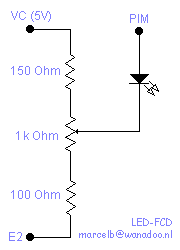
As you can see this is basically the same as the "two diodes and a trim pot" design, with a few minor enhancements. Like that one, it operates as follows. You basically set a voltage using the pot. That voltage plus the voltage drop across the diode is your cut-off point. If the MAP sensor signal (PIM pin on ECU) exceeds that, current starts to flow into the pot, which causes the MAP sensor output voltage to drop because the MAP sensor signal is rather high impedance. Because current is bled off thru resistors, unlike with the Zener FCD where current is bled straight to ground, cutoff is not "sharp". Output voltage continues to rise with MAP sensor signal, only at a much slower pace. This means you can dial it in to hit fuel cut at higher voltage than stock, instead of disabling it completely.
Of course this only works while the stock MAP sensor hasn't topped out yet. Richard Doig's website shows response curves for stock 3SGTE MAP sensors in the tech section. You can see the 91 3SGTE sensor maxes out at 17-18 psi, so if you try to set fuel cut beyond that point, fuel cut will end up being disabled completely.
I used a LED instead of two diodes as in the original design, because a LED has about the same voltage drop as two "normal" diodes and can be used as a warning light if you like. If you don't want a warning light, just hide it or use two "normal" diodes in series instead. If you think cutoff is too soft and MAP signal is being affected too far down the curve (that can happen if you have it set real high) you could add more diodes or another LED and adjust the resistor and pot values to compensate. Don't be surprised if it becomes a challenge to adjust, which is the reason why I didn't do it. I am not concerned about affecting MAP sensor signal a bit down the curve though. If your engine survives 15 psi while the ECU thinks it's running only 12 psi, IMO it will also survive 10 psi while it thinks it runs 8-9 psi.
The resistor on the 5V side of the pot was added to reduce "dead travel" in the pot, making adjustment a bit less sensitive. Since the PIM signal has to overcome the LED anyway, it is no use to set the pot to 4.9 volts, so I added that resistor to lower the starting point a bit. It could have been larger, perhaps even using a smaller pot too, but I wanted to retain the option of completely disabling the FCD just by turning the pot completely to the 5V side.
The other resistor was added for protection. Setting the pot that low would basically short the signal to ground, possibly frying both the LED and the MAP sensor. The resistor offers some protection from misadjustment and widens useable pot travel.